Simple Not Gate Circuit Diagram Nand Inverter Circuit Diagra
Simple not gate circuit Simple not gate circuit Circuit diagram of not gate
Simple Not Gate Circuit
Gate not circuit logic gates input operation analysis diode digital Logic gate circuit drawer Circuit diagram and gate
Simple not gate circuit
What is a not gate?Full adder logic gate circuit diagram template logic logic gates Gate transistorNand inverter circuit diagram simple free download.
Simple not gate circuitGate not circuit transistor logic inverter using truth table 12+ not gate circuit diagramCircuit of not gate.
![Simple Not Gate Circuit](https://i2.wp.com/www.allaboutcircuits.com/uploads/articles/practical-inverter-not-circuit.jpg)
Simple "not gate" scheme
Circuit diagram not gate using transistorWorking of not gate using transistor Simple not gate circuitAnd or not gate circuit diagram.
And gate schematic diagramAnd or not gate circuit diagram 4 not gate circuit diagram on breadboard 2k23Scheme fritzing.
![And Gate Schematic Diagram](https://i2.wp.com/mainetreasurechest.com/wp-content/uploads/2018/05/xor-gate-circuit-diagram-awesome-circuit-for-not-gate-wiring-diagram-ponents-of-xor-gate-circuit-diagram.jpg)
Internal circuit diagram of logic gates
Logic circuit diagram examples » wiring diagramSimple not gate circuit Not gate circuit diagram using diodeTtl circuit of not gate.
The not gateSimple not gate circuit Not gate circuitGate not circuit.
![Ttl Circuit Of Not Gate - Circuit Diagram](https://i2.wp.com/www.vedantu.com/question-sets/f6b02a33-7b4a-4281-974e-46e122ffeb874155025550617684001.png?strip=all)
Diagram gate cmos circuit ic clip vector logic input circuits gates svg hex boolean clker pinout integrated using large datasheet
Gate switching logic illustratesSimple not gate circuit Simple "not gate" schemeInternal circuit diagram of not gate.
Circuit diagram of and gateGates scheme logic What is not gate inverter, not logic gate inverter circuit using transistor[diagram] simple circuit diagram with explanation.
![Simple "Not Gate" Scheme](https://i2.wp.com/trekto.info/f/not-gate/Not-Gate-diagram.jpg)
Gate circuitglobe logic
Simple not gate circuit .
.
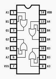
![circuit diagram and gate](https://2.bp.blogspot.com/-xI_9bNSfWg0/Ute8MQYzmMI/AAAAAAAAOtM/mWIYBIt3n0M/s1600/circuit+diagram+and+gate.jpg)
![Simple Not Gate Circuit](https://i2.wp.com/i.stack.imgur.com/nBbox.png)
![Working of NOT Gate using transistor](https://i2.wp.com/www.engineersgarage.com/wp-content/uploads/2019/07/Circuit-Diagram-Transistor-based-NOT-Gate.jpg)
![Simple Not Gate Circuit](https://i2.wp.com/www.dummies.com/wp-content/uploads/311277.image0.jpg)
![Simple "Not Gate" Scheme](https://i2.wp.com/trekto.info/f/not-gate/not-gate-circuit.jpg)
![Simple Not Gate Circuit](https://i2.wp.com/circuitdigest.com/sites/default/files/projectimage/NOT-Gate-using-Transistor.jpg)
![Simple Not Gate Circuit](https://i2.wp.com/www.petervis.com/Education/logic-gates/transistor-logic-not-gate-inverter/transistor-logic-not-gate-circuit.gif)
![Circuit Diagram Not Gate Using Transistor - Circuit Diagram](https://i2.wp.com/www.allaboutcircuits.com/uploads/articles/NOT-gate-circuit-operation-analysis-high-input.jpg?strip=all)